
NEWS: ATE Continuity Testing Fundamentals
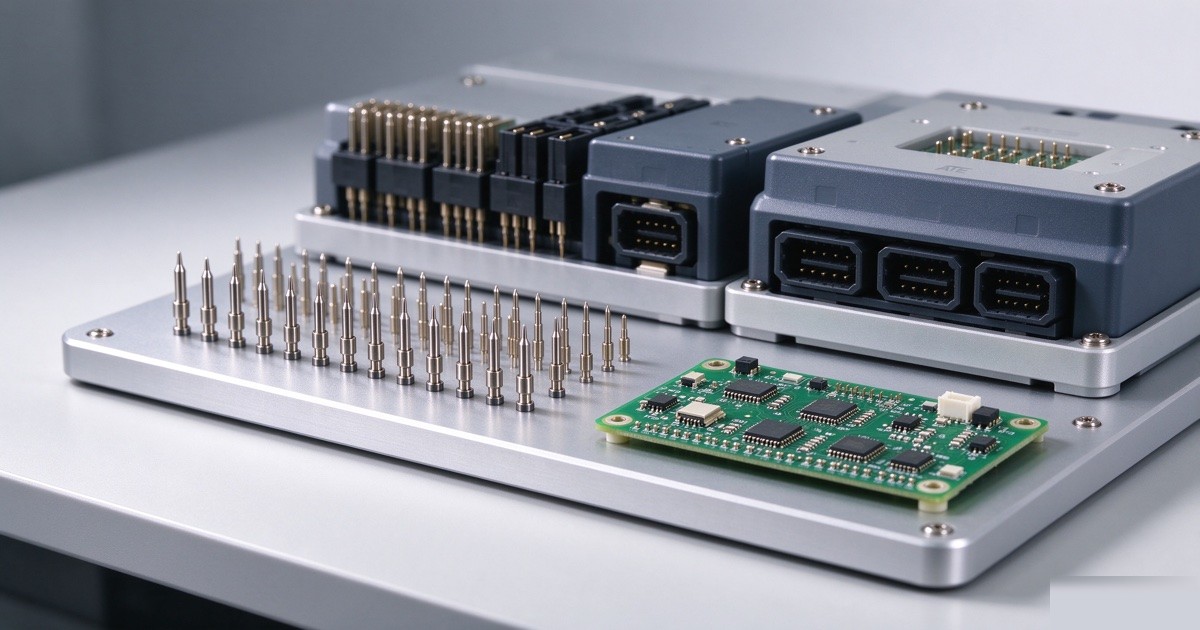
PCTEL is adding Wi-Fi 6/6E coverage testing to its SeeHawk Touch software, with support across 2.4, 5 and 6 GHz channels, as Electronics Weekly reported. The radio detail is different, but the test principle is familiar to anyone who has run a production floor: before you trust a measurement, prove the path. That is the same starting point behind continuity testing in semiconductor ATE: fundamentals and test methods, the first check in most device flows because a bad contact can make a good chip look dead.
Continuity testing answers a plain question. Is the device under test actually connected to the tester? On paper it sounds too simple to matter. In practice it protects yield data, prevents needless retest, and keeps a marginal socket from quietly eating margin for weeks.
What the Wi-Fi coverage story has in common with ATE continuity
SeeHawk Touch is aimed at proving that a network really covers the area and bands a user expects. ATE continuity does the narrower version inside a handler or probe cell: it proves each pin reaches the tester electronics through the load board, socket, pogo pins, relays and cabling. If that chain has an open, a short to a neighbor, or a tired contact with a few ohms of resistance, later tests become theater.
I have seen line stoppages blamed on “bad lots” that turned out to be fixture wear. One common pattern: a power device passes at room temperature, then fails continuity at the hot corner because socket spring force drops and contact resistance creeps up. The chip was fine. The interface was not.
Continuity testing in semiconductor ATE: fundamentals buyers should know
The usual method is simple. Use the ATE pin electronics, often a PPMU or PMU mode, to force a small current and measure voltage, or force a voltage and watch current. Many flows look for the forward drop of ESD structures to supply or ground. A connected pin often lands near a diode drop, roughly 0.4 V to 0.8 V depending on the device and current. An open pin rails or sits near the forced limit. A short sits near 0 V or drags a neighbor down.
Numbers vary by tester family, device technology and fixture design, so treat these as bench starting points, not gospel:
| Check item | Typical starting value | What a miss suggests |
|---|---|---|
| Force current | 100 µA to 1 mA per pin | Too high can stress ESD cells; too low makes leaky pins look open |
| Measure window | -1.5 V to +1.5 V around expected drop | Wide windows hide weak contacts; narrow windows cause false opens |
| Expected ESD drop | 0.4 V to 0.8 V | Near 0 V points to short; near rail points to open or wrong pin map |
| Contact resistance goal | Below 1 Ω for power and ground paths | Higher values shift later leakage, IDD and output tests |
| Settling time | 1 ms to 5 ms before measure | Fast programs misread capacitive pins and long fixture traces |
| Guard check | Adjacent pins held to known state | Finds solder splash, bent leads and socket debris |
The buyer’s angle is not the equation. It is repeatability. Ask how the fixture is cleaned, how often contact resistance is logged, whether the program has a golden-DUT check at shift start, and what happens after a handler jam. A continuity limit that is never reviewed becomes a junk drawer.
Why it matters for component buyers and distributors
Continuity failures create two expensive lies. First, good parts get scrapped or downgraded because the interface lied. Second, bad parts slip through when an open pin masks a real leakage or functional failure. Both show up later as RMA noise, awkward lot-trace calls and a customer asking why date codes “changed behavior” after a socket swap.
When you source ICs through the open market, continuity discipline is a cheap authenticity screen. It will not prove a part is original, but it catches sloppy handling fast: bent leads on fine-pitch QFPs, contaminated BGA balls, moisture-damaged pins, mixed trays with one wrong device. At XingHuan International, we tell buyers to pair incoming inspection with a basic electrical path check where practical, then keep photos, lot codes and fixture IDs tied to the result. Paperwork matters, but so does contact physics.
Short supply makes this sharper. If a MCU, PMIC or FPGA has a 20-week lead time, nobody wants to burn two days arguing over a false failure caused by a worn pogo block. The same goes for refurbished ATE or third-party load boards. A lower price is fine if calibration, relay life and spare-pin mapping are documented. It is not fine when “tested” means “powered once.”
Practical sourcing checks before you blame the silicon
- Confirm the pin map against the current datasheet, not last year’s symbol. Package variants love to move NC pins.
- Log socket cycles and contact resistance. Replace by data, not by someone’s calendar guess.
- Run a known-good device at shift start and after any jam, ESD event or handler maintenance.
- Check force current against absolute maximum ratings and ESD structure limits before tightening limits.
- Separate opens from shorts in fail reports. “Continuity fail” alone is not actionable.
- For brokers or independents, ask for lot traceability, moisture-sensitivity handling and whether parts were baked or repacked.
Context beyond the tester is worth a skim this month. Everspin’s CXL demo put a 4-GB persistent MRAM tier between DRAM and NAND, which raises new board-level and validation questions for memory buyers. Cuffless blood-pressure designs show how sensor, algorithm and custom hardware choices collide, as EDN’s review makes clear. The UK MOSAIC-5G multi-vendor project is another reminder that interoperability claims need measurement. Even an EE Times webinar on audio-based access controls circles back to component selection and application limits. Different products, same habit: prove the interface before arguing about performance.
Common pitfalls that still bite experienced teams
The biggest one is over-tight limits. Engineers try to catch every marginal contact and end up failing humid mornings, long cables and capacitive pins. The second is ignoring ground continuity because “the part powered up.” A weak ground return can pass continuity and still wreck analog measurements later.
Another pitfall is treating continuity as a one-time NPI gate. Fixtures age. Sockets collect dust. Operators change. If your Cpk on later parametric tests drifts while continuity fail rate stays flat, look at the interface before you look at the wafer lot.
FAQ
Q: What current should I use for ATE continuity testing?
A: Start around 100 µA to 1 mA per pin unless the device datasheet says otherwise. Stay clear of ESD and absolute-max limits, and lower the current for sensitive RF or high-voltage pins.
Q: Can continuity testing detect counterfeit ICs?
A: It can flag handling damage, wrong packages, broken bonds and mixed trays, but it cannot prove origin. Use it with lot codes, date-code logic, packaging inspection and, when risk is high, decap or X-ray through a qualified lab.
Q: Why do continuity fails rise after a handler jam?
A: Jams bend pogo pins, smear debris across contacts and knock the DUT off its true seat. Re-run a golden device, inspect the socket under magnification and check contact resistance before releasing the lot.